Waveshare Raspberry Pi Pico Entry Level Kit | All-in-One Expansion Board with 15 Common Sensors Module

Original price was: ₨20,500.00.Current price is: ₨19,500.00.

23 Items sold in last 3 months
  • Delivery to Pakistan

Shipping via Leopards

1-3 Business Days (Normally)

Shipping calculated at checkout.

  • Delivery to US

Shipping via DHL, UPS, or FedEx.

3-12 Business Days (Normally)

Shipping calculated at checkout.

Payment Methods:

Overview

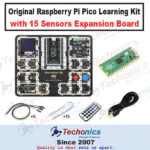
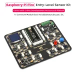
This Waveshare Pico-Sensor-Kit is a comprehensive, all-in-one electronic starter pack designed for the Raspberry Pi Pico. It features a unique “break-away” PCB design that allows you to start coding immediately without messy wiring.

Key Product Highlights:

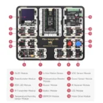
  • Complete All-in-One Solution: Includes a pre-soldered Raspberry Pi Pico (with headers), a specialized expansion board, and 15 integrated modules on a single PCB.

  • Includes Original Raspberry Pi Pico Development Module.
  • Plug-and-Play Design: No soldering or breadboarding is required for initial use. The modules are pre-connected to the Pico via PCB traces for an “out-of-the-box” experience.

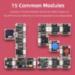
  • Modular Versatility: While it comes as a single unit, each of the 15 modules can be snapped off and used independently with the included cables for custom projects.

  • 15 Essential Modules: Features a wide variety of sensors and outputs including:

    • Visuals: OLED display, RGB LED, and standard LED.

    • Sensors: 6-axis motion, VOC gas, light (LDR), sound, and temperature/humidity.

    • Controls: Motor driver, potentiometer, button, and IR transmitter/receiver.

    • Logic & Storage: EEPROM and a passive buzzer.

  • Rich Documentation: Provides standard , UART, and GPIO interfaces with clearly labeled addresses on the board, making it ideal for learning MicroPython or C/C++ programming.

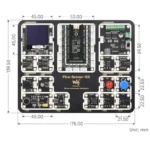
  • Compact Footprint: The entire board measures 175mm x 139.5mm, making it a tidy and portable workstation for students and hobbyists.

Detailed Description


The Waveshare Pico-Sensor-Kit is designed as a bridge between beginner coding and advanced hardware integration. The board is divided into logical zones, with the Raspberry Pi Pico acting as the brain in the center.

Getting Started: How to Use the Kit

  1. Preparation: Plug the included Raspberry Pi Pico into the center slot. Connect the kit to your computer via the USB cable.

  2. Coding Environment: Use an IDE like Thonny to program in MicroPython or Arduino IDE for C++.

  3. Communication: Most sensors on this board communicate via the I2C protocol. Notice the specific addresses (e.g., 0x3D for OLED) printed directly on the PCB next to the modules.

  4. Separation: If you want to build a standalone device (like a small robot), you can physically snap the modules off the board and reconnect them using the provided 4-pin cables.


Module Breakdown & Usage Guide

# Module Use Case & Connection Type How to Use It
1 OLED Display pixels (I2C) Display text, sensor data, or simple graphics.
2 6-Axis Motion Accelerometer + Gyro (I2C) Detect tilt, shake, or orientation for gaming/stabilization.
3 VOC Sensor Air Quality (I2C) Measure volatile organic compounds to monitor indoor air.
4 Potentiometer Analog Input (ADC) A turn-knob to control volume or LED brightness.
5 Photoresistor (LDR) Light Sensor (ADC) Detect ambient light levels to make an auto-nightlight.
6 Sound Sensor Microphone (ADC/Digital) Detect claps or measure noise levels in a room.
7 RGB LED Full-color Light (Digital) Mix Red, Green, and Blue to create any color light.
8 Buzzer Audio Output (PWM) Play simple melodies, beeps, or alarms.
9/10 IR TX / RX Infrared Link (Digital) Send/receive remote control signals (TV remote style).
11/12 Button & LED Digital Input/Output The “Hello World” of hardware: press button to toggle light.
13 Temp & Humid SHTC3 Sensor (I2C) Build a digital weather station or smart thermostat.
14 EEPROM Memory Storage (I2C) Save settings or data logs even after power is turned off.
15 Motor Driver Dual Bridge (I2C/PWM) Control the speed and direction of two DC motors.


Pin Layout & Communication

The kit is intelligently routed so that multiple sensors share the I2C bus without conflict.

  • I2C0 Bus: Controls the Motor Driver, EEPROM, and Temp/Humidity sensors.

  • I2C1 Bus: Controls the OLED and Motion sensors.

  • ADC Pins: Used by the Potentiometer, LDR, and Sound sensor to provide variable voltage readings from to .

How to use every module?

To keep your code organized, ensure you have the Raspberry Pi Pico firmware installed. Since many of these modules use I2C, we first initialize the I2C bus.

Most modules on this board are hard-wired to specific pins. For the examples below, we assume standard Pico-Sensor-Kit wiring: I2C0 (SDA GP0, SCL GP1) and I2C1 (SDA GP6, SCL GP7).


1. OLED Display (Module 1)

Note: Requires the ssd1306.py library.

Python

 
from machine import Pin, I2C
import ssd1306

i2c = I2C(1, sda=Pin(6), scl=Pin(7)) # I2C1 for OLED
display = ssd1306.SSD1306_I2C(128, 64, i2c, addr=0x3D)

display.text('Hello Pico!', 0, 0)
display.show()

2. 6-Axis Motion & VOC (Modules 2 & 3)

These return raw hex data over I2C.

Python

 
# Scan for addresses to ensure they are seen (Motion: 0x68, VOC: 0x59)
print("I2C Scan:", [hex(i) for i in i2c.scan()])

3. Potentiometer, LDR, & Sound (Modules 4, 5, 6)

These use the Analog-to-Digital Converter (ADC).

Python

 
from machine import ADC
import time

pot = ADC(26) # Potentiometer (ADC0)
ldr = ADC(27) # Light Sensor (ADC1)

while True:
    print("Pot:", pot.read_u16(), "Light:", ldr.read_u16())
    time.sleep(0.5)

4. RGB LED (Module 7)

Uses PWM to mix colors.

Python

 
from machine import Pin, PWM

red = PWM(Pin(16)) # Example pin
red.freq(1000)
red.duty_u16(32768) # 50% brightness

5. Passive Buzzer (Module 8)

Python

 
from machine import Pin, PWM
import time

buzzer = PWM(Pin(18))
def play_tone(freq):
    buzzer.freq(freq)
    buzzer.duty_u16(1000) # Volume
    time.sleep(0.5)
    buzzer.duty_u16(0)

play_tone(440) # Play Note A

6. Button & LED (Modules 11 & 12)

Classic digital input and output.

Python

 
from machine import Pin

led = Pin(20, Pin.OUT)
button = Pin(21, Pin.IN, Pin.PULL_UP)

while True:
    if not button.value(): # If button pressed
        led.on()
    else:
        led.off()

7. Temperature & Humidity (Module 13)

Note: Uses I2C0 (Addr: 0x70).

Python

 
i2c0 = I2C(0, sda=Pin(0), scl=Pin(1))
# Sending measurement command to SHTC3
i2c0.writeto(0x70, b'\x7C\xA2') 

8. Motor Driver (Module 15)

The motor driver uses an I2C-to-PWM chip (usually PCA9685 at 0x40).

Python

 
# Basic logic to set a motor pin high via I2C0
i2c0.writeto_mem(0x40, 0x06, b'\x00\x00\xff\x07') # Example full-on command

Summary of Pin Connections
Component Interface Pico Pins (Default)
I2C0 Bus Motor, Temp, EEPROM SDA (GP0), SCL (GP1)
I2C1 Bus OLED, 6-Axis, VOC SDA (GP6), SCL (GP7)
Analog Pot, LDR, Sound GP26, GP27, GP28
Digital Buttons, LEDs, IR GP14 – GP22


Customer Reviews

0 reviews
0
0
0
0
0

There are no reviews yet.

Be the first to review “Waveshare Raspberry Pi Pico Entry Level Kit | All-in-One Expansion Board with 15 Common Sensors Module”
SKU: Raspberry-Pi-Pico-15-Sensor-Kit-Expansion-Board Categories: , , , Tags: , ,