

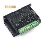
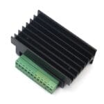
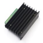
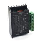


TB6600 4A 9V-42V DC Microstep Stepper Motor Driver
The TB6600 Microstep Stepper Motor Driver is a high-performance, single-axis digital stepper driver designed for controlling 2-phase and 4-phase hybrid stepper motors (such as NEMA 17, NEMA 23, and NEMA 24). Operating on a wide input voltage range of 9V to 42V DC and delivering up to 4.0A peak output current, this driver is a standard choice for CNC routers, 3D printers, laser cutters, and industrial automation equipment.
Equipped with an integrated heavy-duty aluminum heatsink, high-speed optocoupler isolation, and 6-bit DIP switches for configuration, the TB6600 delivers smooth motor rotation, low resonance noise, and high positioning accuracy.
Key Features & Technical Highlights
-
High-Speed Optocoupler Signal Isolation: High-speed optical isolation on signal inputs (PUL, DIR, ENA) prevents high-voltage motor electrical noise from feeding back into sensitive microcontrollers, PLCs, or CNC interface boards.
-
Adjustable Microstep Resolution: 6-bit DIP switches allow on-the-fly microstep selection (up to 1/32 step / 6400 pulses/rev) for low-vibration operation and fine movement control.
-
Selectable Current Output: Current levels can be set from 0.5A up to 4.0A (peak) via onboard DIP switches to prevent motor overheating.
-
Heavy-Duty Heat Dissipation: Designed with a thick black aluminum heatsink frame to maintain stable thermal performance during continuous operation.
-
Full Protection Suite: Includes built-in safeguards against over-current, under-voltage lockout (UVLO), over-voltage, and thermal protection (TSD).
Technical Specifications
| Parameter | Specification |
| Input Supply Voltage (VCC) | 9V – 42V DC (24V – 36V DC Recommended) |
| Output Peak Current (I out) | 0.5A – 4.0A (Adjustable) |
| Supported Microstep Modes | 1 (Full), 2/A, 2/B, 4, 8, 16, 32 (Up to 6400 pulses/rev) |
| Control Signal Input Voltage | 3.3V – 24V DC (Requires series resistor if >5V on standard inputs) |
| Maximum Pulse Frequency | 20kHz |
| Compatible Motors | 2-Phase / 4-Phase NEMA 17, NEMA 23, NEMA 24 (4, 6, or 8-lead) |
| Cooling Method | Passive Aluminum Heatsink Base |
| Operating Temperature | -10°C to +45°C |
DIP Switch Settings & Configuration Guide
The onboard 6-bit DIP switch block manages microstep resolution (SW1–SW3) and output current limits (SW4–SW6).
1. Microstep Selection (SW1, SW2, SW3)
| Microstep | Pulses/Rev | SW1 | SW2 | SW3 |
| NC | NC | ON | ON | ON |
| 1 (Full) | 200 | ON | ON | OFF |
| 2/A | 400 | ON | OFF | ON |
| 2/B | 400 | ON | OFF | OFF |
| 4 | 800 | OFF | ON | ON |
| 8 | 1600 | OFF | ON | OFF |
| 16 | 3200 | OFF | OFF | ON |
| 32 | 6400 | OFF | OFF | OFF |
2. Peak Current Selection (SW4, SW5, SW6)
| Peak Current | RMS Current | SW4 | SW5 | SW6 |
| 0.5A | 0.45A | ON | ON | ON |
| 1.0A | 0.90A | ON | OFF | ON |
| 1.5A | 1.35A | ON | ON | OFF |
| 2.0A | 1.80A | ON | OFF | OFF |
| 2.5A | 2.25A | OFF | ON | ON |
| 2.8A | 2.50A | OFF | OFF | ON |
| 3.0A | 2.70A | OFF | ON | OFF |
| 3.5A / 4.0A | 3.20A | OFF | OFF | OFF |
Terminal Pinout & Wiring Guide
Power & Motor Terminals (High Voltage)
-
VCC: Connect to 9V – 42V DC Positive (+) power supply.
-
GND: Connect to Power Supply Ground (-).
-
A+ / A-: Connect to Stepper Motor Phase A coil leads.
-
B+ / B-: Connect to Stepper Motor Phase B coil leads.
Signal Terminals (Low Voltage Control)
-
PUL+ / PUL- (CLK): Pulse Input signal. Controls motor step movement.
-
DIR+ / DIR-: Direction Input signal. High level = clockwise; Low level = counter-clockwise.
-
ENA+ / ENA-: Enable Input signal. Disables coil current when activated (allows manual shaft rotation).
Note: For Common Cathode connection, tie PUL-, DIR-, and ENA- to microcontroller GND and drive PUL+, DIR+, and ENA+ with GPIO pins. For Common Anode connection, tie PUL+, DIR+, and ENA+ to $5\text{V}$ and sink signals via PUL-, DIR-, and ENA-.
Recommended Applications
-
CNC Machinery: Small to mid-scale CNC routers, milling machines, and engraving tables.
-
3D Printers & Additive Manufacturing: Industrial-grade or large-format 3D printer axis drives.
-
Automated Pick & Place Systems: Linear actuators, conveyor belts, and automated slide tables.
-
Camera Sliders & Pan-Tilt Rigs: Motorized filming equipment requiring quiet operation and smooth motion curves.