


Description:
This is an open-source code base and Simple io platform, and with the use of a similar java, C language development environment. So you can quickly use the language with Flash or Processing … and other software to make interactive works. Can be used to complete the development of electronic components such as Switch or Sensors or other controllers, LED, stepper motor or other output devices.
You can also operate independently as a software platform that can communicate with, for example, said: flash processing Max / MSP VVVV or other interactive software … to develop an open-source IDE interface is based on the principle that allows you to download free of charge to develop more surprising interactive work.
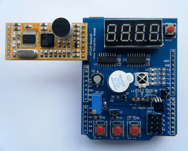
Multi-function Shield has the following characteristics:
- With the market, 2009 UNO LENARDO 2560 controller seamlessly mainstream
- 4-way LED indicator (LED indicator to know the importance, in the actual doing projects, with this indicator can be used directly working status LED indicates the procedure to facilitate debugging.
- DS18B20 temperature sensor interface that can be done to measure the temperature of the experiment, this price does not include the DS18B20 Oh, needed another shot.
- LM35 temperature sensor interface that can be done to measure the temperature of the experiment, this price does not include LM35 Oh, needed another shot. 5,3296 precision adjustable potentiometer, analog input port (can be used for controlling LED brightness, turn the steering angle, the digital voltage, etc.)
- The integrated infrared receiver that can fit any infrared remote control experiments, the price also does not include the integrated receiver and needed another shot.
- Four digital tubes (using 74HC595 driver provincial IO learning SPI), you can do digital display experiment (can display temperature, voltage, counter value, etc.).
- Three separate buttons, a reset button, the button can do experiments (HMI).
- The buzzer sound can be used for experiments. (Can call the police, pronunciation, etc.)
- Bluetooth, wireless interfaces, voice module, voice recognition module can be used for wireless communication experiments.
- servo interface, easy to drive servos
- infrared detection interface, easy and infrared docking realization of human traffic statistics, etc.
Code Examples:
********************************************************************
Blinking LED
1 2 3 4 5 6 7 8 9 10 11 12 13 14 15 | int led = 13;void setup(){// initialize the digital pin as an output.pinMode(led, OUTPUT);}void loop(){digitalWrite(led, HIGH);delay(1000);digitalWrite(led, LOW);delay(1000);} |
********************************************************************
All LEDS blinking
1 2 3 4 5 6 7 8 9 10 11 12 13 14 15 16 17 18 19 20 21 22 23 24 25 26 27 | int led1 = 13;int led2 = 12;int led3 = 11;int led4 = 10;void setup(){// initialize the digital pin as an output.pinMode(led1, OUTPUT);pinMode(led2, OUTPUT);pinMode(led3, OUTPUT);pinMode(led4, OUTPUT);}void loop(){digitalWrite(led1, HIGH);digitalWrite(led2, HIGH);digitalWrite(led3, HIGH);digitalWrite(led4, HIGH);delay(1000);digitalWrite(led1, LOW);digitalWrite(led2, LOW);digitalWrite(led3, LOW);digitalWrite(led4, LOW);delay(1000);} |
********************************************************************
Switches example
1 2 3 4 5 6 7 8 9 10 11 12 13 14 15 16 17 18 19 20 21 22 23 24 25 26 27 28 29 30 31 32 33 | const byte LED[] = {13,12,11,10};#define BUTTON1 A1#define BUTTON2 A2void setup(){// initialize the digital pin as an output./* Set each pin to outputs */pinMode(LED[0], OUTPUT);pinMode(LED[1], OUTPUT);pinMode(LED[2], OUTPUT);pinMode(LED[3], OUTPUT);}void loop(){if(!digitalRead(BUTTON1)){digitalWrite(LED[0], HIGH);digitalWrite(LED[1], HIGH);digitalWrite(LED[2], HIGH);digitalWrite(LED[3], HIGH);}if(!digitalRead(BUTTON2)){digitalWrite(LED[0], LOW);digitalWrite(LED[1], LOW);digitalWrite(LED[2], LOW);digitalWrite(LED[3], LOW);}} |
********************************************************************
Potentiometer 1
1 2 3 4 5 6 7 8 9 10 11 12 13 14 15 16 | #define Pot1 0void setup(){Serial.begin(9600);}/* Main Program */void loop(){Serial.print(?Potentiometer reading: ?);Serial.println(analogRead(Pot1));/* Wait 0.5 seconds before reading again */delay(500);} |
********************************************************************
Pot and led
1 2 3 4 5 6 7 8 9 10 11 12 13 14 15 16 17 18 19 20 21 22 23 24 25 26 27 28 29 30 31 32 33 34 35 36 37 38 39 40 41 | const byte LED[] = {13,12,11,10};#define Pot1 0void setup(){Serial.begin(9600);// initialize the digital pin as an output./* Set each pin to outputs */pinMode(LED[0], OUTPUT);pinMode(LED[1], OUTPUT);pinMode(LED[2], OUTPUT);pinMode(LED[3], OUTPUT);}/* Main Program */void loop(){int PotValue;//Serial.print(?Potentiometer reading: ?);PotValue = analogRead(Pot1);/* Wait 0.5 seconds before reading again */if(PotValue < 400){digitalWrite(LED[0], LOW);digitalWrite(LED[1], LOW);digitalWrite(LED[2], LOW);digitalWrite(LED[3], LOW);Serial.print(?Potentiometer: ?);Serial.println(PotValue);}else{digitalWrite(LED[0], HIGH);digitalWrite(LED[1], HIGH);digitalWrite(LED[2], HIGH);digitalWrite(LED[3], HIGH);Serial.print(?Potentiometer: ?);Serial.println(PotValue);}delay(500);} |
********************************************************************
segment display
1 2 3 4 5 6 7 8 9 10 11 12 13 14 15 16 17 18 19 20 21 22 23 24 25 26 27 28 29 30 31 32 33 34 35 36 37 | /* Define shift register pins used for seven segment display */#define LATCH_DIO 4#define CLK_DIO 7#define DATA_DIO 8/* Segment byte maps for numbers 0 to 9 */const byte SEGMENT_MAP[] = {0xC0,0xF9,0xA4,0xB0,0x99,0x92,0x82,0xF8,0X80,0X90};/* Byte maps to select digit 1 to 4 */const byte SEGMENT_SELECT[] = {0xF1,0xF2,0xF4,0xF8};void setup (){/* Set DIO pins to outputs */pinMode(LATCH_DIO,OUTPUT);pinMode(CLK_DIO,OUTPUT);pinMode(DATA_DIO,OUTPUT);}/* Main program */void loop(){/* Update the display with the current counter value */WriteNumberToSegment(0 , 0);WriteNumberToSegment(1 , 1);WriteNumberToSegment(2 , 2);WriteNumberToSegment(3 , 3);}/* Write a decimal number between 0 and 9 to one of the 4 digits of the display */void WriteNumberToSegment(byte Segment, byte Value){digitalWrite(LATCH_DIO,LOW);shiftOut(DATA_DIO, CLK_DIO, MSBFIRST, SEGMENT_MAP[Value]);shiftOut(DATA_DIO, CLK_DIO, MSBFIRST, SEGMENT_SELECT[Segment] );digitalWrite(LATCH_DIO,HIGH);} |
********************************************************************
Read pot and display value on display
1 2 3 4 5 6 7 8 9 10 11 12 13 14 15 16 17 18 19 20 21 22 23 24 25 26 27 28 29 30 31 32 33 34 35 36 37 38 39 40 41 42 43 | /* Define shift register pins used for seven segment display */#define LATCH_DIO 4#define CLK_DIO 7#define DATA_DIO 8#define Pot1 0/* Segment byte maps for numbers 0 to 9 */const byte SEGMENT_MAP[] = {0xC0,0xF9,0xA4,0xB0,0x99,0x92,0x82,0xF8,0X80,0X90};/* Byte maps to select digit 1 to 4 */const byte SEGMENT_SELECT[] = {0xF1,0xF2,0xF4,0xF8};void setup (){Serial.begin(9600);/* Set DIO pins to outputs */pinMode(LATCH_DIO,OUTPUT);pinMode(CLK_DIO,OUTPUT);pinMode(DATA_DIO,OUTPUT);}/* Main program */void loop(){int PotValue;PotValue = analogRead(Pot1);Serial.print(?Potentiometer: ?);Serial.println(PotValue);/* Update the display with the current counter value */
|


Reviews
Clear filtersThere are no reviews yet.