Description:
The Bluefruit LE UART Friend makes it easy to add Bluetooth Low Energy connectivity to anything with a hardware or software serial port. Connect to your Arduino or other microcontroller or even just a standard FTDI cable for debugging and testing.
This multi-function module can do quite a lot! For most people, they’ll be very happy to use the standard Nordic UART RX/TX connection profile. In this profile, the Bluefruit acts as a data pipe, that can ‘transparently’ transmit back and forth from your iOS or Android device. There is even a nice hardware flow control so you won’t have to think about losing data.
The board is capable of much more than just sending strings over the air. Thanks to an easy to learn AT command set, you have full control over how the device behaves, including the ability to define and manipulate your own GATT Services and Characteristics, or change the way that the device advertises itself for other Bluetooth Low Energy devices to see. You can also use the AT commands to query the die temperature, check the battery voltage, and more, check the connection RSSI or MAC address, and a whole lot more.
Power Pins
- VIN: This is the power supply for the module, supply with 3.3-16V power supply input. This will be regulated down to 3.3V to run the chip
- GND: The common/GND pin for power and logic
UART Pins
- TXO – This is the UART Transmit pin out of the breakout (Bluefruit LE –> MCU), it’s at 3.3V logic level.
- RXI – This is the UART Receive pin into the breakout (MCU –> Bluefruit LE). This has a logic level shifter on it, you can use 3-5V logic.
- CTS – Clear to Send hardware flow control pin into the the breakou (MCU –> Bluefruit LE). Use this pin to tell the Bluefruit that it can send data back to the microcontroller over the TXO pin. This pin is pulled high by default and must be set to ground in order to enable data transfer out! If you do not need hardware flow control, tie this pin to ground it is a level shifted pin, you can use 3-5V logic
- RTS – Read to Send flow control pin out of the module (Bluefruit LE –> MCU). This pin will be low when its fine to send data to the Bluefruit. In general, at 9600 baud we haven’t seen a need for this pin, but you can watch it for full flow control! This pin is 3.3V out
Other Pins
- MOD: Mode Selection. The Bluefruit has two modes, Command and Data. You can keep this pin disconnected, and use the slide switch to select the mode. Or, you can control the mode by setting this pin voltage, it will override the switch setting! High = Command Mode, Low = UART/DATA mode. This pin is level shifted, you can use 3-5V logic
- DFU: Setting this pin low when you power the device up will force the Bluefruit LE module to enter a special firmware update mode to update the firmware over the air. Once the device is powered up, this pin can also be used to perform a factory reset. Wire the pin to GND for >5s until the two LEDs start to blink, then release the pin (set it to 5V or logic high) and a factory reset will be performed.
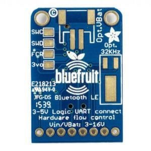
Reverse Side Breakouts
On the back we also have a few breakouts!
Opt VBat: If you fancy, you can solder on a JST 2-PH connector, this will let you easily plug in a Lithium Ion or other battery pack. This connector pad is diode protected so you can use both Vin and VBat and the regulator will automatically switch to the higher voltage
Opt. 32 KHz: If you’re doing some funky low power work, we wanted to give you the option of solderin in a 32khz oscillator. Our firmware doesn’t support it yet but its there!
SWC: This is the SWC clock pin, 3v logic – for advanced hackers!
SWD: This is the SWD data pin, 3v logic – for advanced hackers!
3Vo: This is the output from the 3V regulator, for testing and also if you really need regulated 3V, up to 250mA available
FCR: This is the factory reset pin. When all else fails and you did something to really weird out your module, tie this pad to ground while powering up the module and it will factory reset. You should try the DFU reset method first.







Reviews
Clear filtersThere are no reviews yet.